


What?
A lighting controller to make the house server look... sparkly.When?
Spring 2004Why?
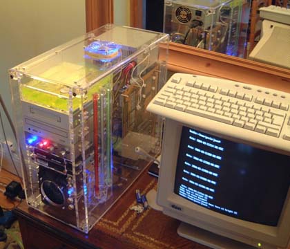
Having elected to house the house server in a nice perspex case, we thought it would be a good idea to put some pretty lights in it. It's sort of traditional, if you're modifying your PC's case. Of course, a few LEDs would probably have done it... I'm just a little excessive.How?
The first task was assembling the case, which came in convenient flat-pack form. We had to be very careful not to scratch anything, but fortunately the kit came with some rather tasty cotton gloves to help out with that. We also remembered to spray the whole thing down with an anti-static solution before we finished - otherwise the motherboard would be heading for toasted-diode heaven.Once the chassis was assembled, the next thing was to load it up with hardware, and then install the water-cooling kit. This was delayed a little while by the need to transfer the old cooling block, processor and motherboard from my desktop machine, and I couldn't do so until Extremecooling got their act together and sent me a new Pentium 4 cooling block. This took longer than you would have thought possible.
Once the bits had arrived, though, it was the usual process of dropping screws into inaccessible places, lining up expansion cards and general twiddling around that you're used to when building a PC. The only non-standard item at this stage was the cooling system, which can be filled with the top panel of the case removed. The U/V dye was added to the water at this point, just for the sheer pleasure of having flexible tubes of bright yellow liquid snaking around the dining room (the pump is on the floor, isolated by AnOldJumperTM).
Then came the tricky bit. Well actually, that's a narrative ploy. I'd been working on the tricky bit in parallel with the rest of the project, but it's easier to recap here than try to explain two things at once. Anyway. With the number of lights I wanted to put into the box, it quickly became apparent that the effect would be much enhanced if they pulsated, or otherwise did something interesting. This pushed me to re-learn some basic electronics, and get thinking about what would be needed.
Essentially, the lighting controller would need 20 or so channels of PWM output, for controlling LEDs. As any of these LEDs could be high-brightness Luxeon types, the current consumption could peak at 5 amps or so, necessitating largish driver transistors. To interface these to a controller (PIC16F627), buffer transistors would also be required, making for Darlington outputs. With 20 outputs in a 5x4 grid, and four channels of on/off control for the cold-cathode tubes, this produced a circuit calling for 26 transistors - quite a challenge to lay out when you're stuck to single-sided PCBs.
I prototyped the basic circuit on Gina's 250-in-one electronics kit, and it all checked out okay - including the serial interface to the host PC, which was running a couple of little Java utilities to output the relevant 26-byte packets. This gave me enough confidence to design the PCB and etch it in the garden shed. Apart from putting the PIC socket on back-to-front (muppet! Good thing PICs are cheap...), the PCB was very straightforwards to debug. It happily controls all the necessary lights, with the PWM channels updating at 100Hz and capable of cycling through 64 intensity levels.
Having installed the board (and lights) into the case, I redeveloped the driver software to link into the LCD controller, allowing the lights to display meaningful information. As it stands, the controller cycles between two modes:
- Pretty-patterns mode, where the lights do various visual effects like colour chasing, strobing etc.
- LCD mode, where the lights display information relevant to the current LCD screen. For example, on the email screen, the speed of the top row of LEDs indicates the quantity of email waiting, and the cold-cathode tubes indicate who it's for. The controller also takes care of shutting down the cold-cathode tubes, to safe on the life of the tubes and also to allow the dining room to occasionally go dark - fairly well lit with all the lights on!
The system is a definite conversation point!